Integration of Python-Based AI Models with Simulation and Hardware Deployment
Ryotaro Abe, TS TECH
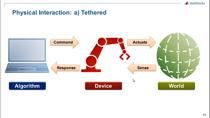
Integrating ECU (electronic control unit) development with OEMs (original equipment manufacturers) in the fast-paced automotive industry presents a significant challenge. TS TECH aims to enhance vehicle interior comfort using AI technology, which requires the integration of vehicle control functions (developed in C language for ECUs) with AI models developed in Python®. They have leveraged MATLAB® and Simulink® to successfully bridge this gap, enabling the creation of complex simulation models, which include AI models, for ECU implementation.
With the support of MathWorks Consulting Services, TS TECH has developed a real-time system for estimating driver fatigue during vehicle operation. This session will detail their journey, focusing on overcoming integration challenges by using MATLAB and Simulink as the core platform. Their approach facilitates the transition from Python to MATLAB and Simulink, and finally to C code, to be suitable for ECU deployment.
You will learn how TS TECH strategically used MATLAB and Simulink to merge high-level AI development with the technical needs of automotive ECUs. You will also gain insight into the algorithms and technologies used, the project's goals, and how MATLAB and Simulink have been instrumental to its' success.
Published: 6 Nov 2024
[AUDIO LOGO]
Hello, everyone. Welcome to my presentation. I am Ryotaro Abe, an engineer from electrical device development of TS TECH. I'm a data scientist in charge of developing algorithms to estimate human states. Today, I would like to present our effort to implement a Python-based model in ECU using MATLAB and Simulink.
So here is the agenda of my presentation today. First, I would like to introduce our company and then I would like to explain the product image for the image we are aiming for the info and fatigue estimation. And then I would like to talk about the implementation of ECU. First, let me introduce our company.
TS TECH mainly manufactures and sells seats for four wheelers and two wheelers. In addition to seat, we also manufacture and sell door trims and lighting devices. Our main customer includes Honda, Suzuki, Volkswagen, and Harley-Davidson, In addition to Japanese motorcycle manufacturers. When you think of car seat, you may imagine we develop seat, seat frame, or seat cushion. However, we are also developing electrical components to make drivers more comfortable like seat heater.
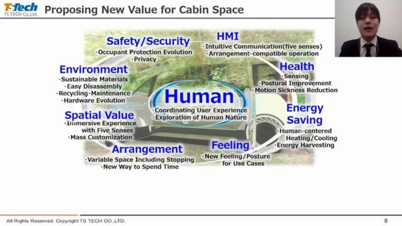
Next, I explain about the products we aim to develop. The seat is the most closely attached part to the passenger in automobile. Through the development of the seat, we have accumulated technology and know how to pass the passenger comfort. In the future, however, with the development of autonomous driving technology, the way people spend their time inside a vehicle will become even more diverse than before.
In order to contribute to the further development of automobiles, we need to provide new human-centered value, not only in the seat, but also in the entire interior space. In order to provide new value for the entire interior space, we believe it is necessary to combine the technology of, not only automobile OEMs and TS TECH but also other interior parts manufacturers, as well as other industries and startups.
However, it is difficult to develop with other industries, not just the automobile industry, due to differences in development environment and culture. Therefore, we are considering using MATLAB or Simulink as an environment for the integration of software-based functions.
In the past, each company had to prepare hardware and much communication specification in order to combine functions. These are our only ancillary tasks to validate the functionality, but this require a lot of effort and time.
If we can incorporate the function of each company into MATLAB or Simulink, combine them in MATLAB or Simulink to verify their operation, and then implement the combined function into the vehicle using automatic code generation, we believe that it will be possible to reduce the human hours required for hardware preparation and specification matching and to conduct feasibility verification at an early stage. We would like to move to such a development system in the future, and this time, we combine the function using MATLAB or Simulink and implemented them in ECU to prove the concept for the purpose.
Next, I explained the products implemented in real time. As mentioned earlier, TS TECH aim to create a comfortable and attractive space centered on human. To focus on human, we believe that it is important to have the technology to know the state of human. The state is a part in an automobile that touch people the most, and we are making use of this advantage to develop sensing technology, especially for estimating the state of people.
We focused on driver fatigue as a first step in developing technology to understand the state of human. In recent years, automobile OEMs have been fiercely engaged in the development of autonomous driving technologies. With the development of autonomous driving technology, advanced driver assistance systems such as adaptive cruise control and traffic jam assist will be adopted in future vehicles, even at low-priced car. And drivers will be able to drive comfortably longer.
On the other hand, if the driving role is reduced, there is a possibility that some driver may not notice their own fatigue or may continue driving, even if they are somewhat tired because they depend on the driver assistance system. In a state of high fatigue, delay and mistake occur in recognition, judgment, operation which may result in an accident.
Therefore, with the development of driver-assistance system, we believe that the development of technology to know the driver's condition will become important. We have therefore started to develop technology to estimate the driver's fatigue and to prevent accidents by detecting the driver's fatigue conditions, such as encouraging the driver to take a break when driving under excessive fatigue.
This is an overview of the fatigue estimation algorithm. Our algorithm estimates the fatigue from the electrocardiogram. The waveform shown in PQRSD represent one heartbeat. This peak is called the R-wave, and the interval between the R-wave is called RRI. The change of RRI is not constant, but fluctuates finally,
It says that the autonomic nervous activity is involved in this fluctuation, and by analyzing this fluctuation, it is generally possible to calculate an index that reflects the state of sympathetic and parasympathetic nerves. The algorithm calculates feature from error fluctuation and estimate fatigue level using machine learning model.
We have been developing algorithm in offline environment. However, as the development continued and the accuracy increased, new problems emerged. The problem is one level of performance and accuracy is required to bring the developed model to market as a product. 70%, 80%, or 90% is the model we build achieving acceptable to users? This problem couldn't be solved by this discussion.
To solve this problem, it is necessary to provide the users with experience of fatigue estimation as a service. By estimating the driver fatigue, while driving and informing them of an increased fatigue, we wanted to know whether users would find the service valuable? To do this, we needed to run the developed algorithm online instead of . From such background, we try to implement the real-time algorithm.
Now I would like to talk about the real-time implementation of algorithm, which is the main topic of today. Let's start with the challenge in implementation of real-time system. Considering the mass-production development flow in the future, it was necessary to implement it in C language to implement it in the in-vehicle ECU.
This time we developed the algorithm, not alone but jointly with other companies. Marabou was our primary development environment, but our partners development environment was Python. And this algorithm was built in the Python environment. Therefore, the Python code needed to be ported to C for the real-time implementation.
However, coding into C by hand, require a lot of time and effort. In addition, when the algorithm needs to be modified through verification, the code written in C will need to be modified, which is expected to take time.
We decided to port the Python code to Marabou and use Simulink's auto code generation to generate C code. It does require code from Python to Marabou, but it's less labor intensive than hand-coded C port. In addition, by incorporating it into our main development environment, we believe it will be possible to combine it with various functions in the future.
This is a road to real-time implementation. First, we port an algorithm written in Python to Marabou. After that, the algorithm ported to Marabou was implemented on Simulink to operate in real time and finally, implemented on ECU using the auto code generation function. In the following section, I will focus on the part of this role that requires special attention.
This is the hardware configuration of the system we developed. With the analog signal from the sensor as input, the model estimation result is output by the count signal, and the result is displayed on the PC. We choose the Raspberry Pi as the ECU because it can be used as an LCP machine, which eliminates the need for hardware development and enable real machine testing in a short period of time and at low cost.
The first topic is porting from Python to Marabou. Porting from Python to Marabou is basically a matter of reading Python code and rewriting it into Marabou. However, there is a point that needs to be noted.
For example, this std() function calculates a standard deviation. Python and MATLAB will have the same function. However, if you actually run it with the same input, the result will be different. Why? This is due to differences in default definitions.
In Python, the std() function calculates the standard deviation by default. Marabou, on the other hand, calculates the invariant standard deviation by default. To make this result consistent, the Marabou code had to be rewritten like this.
Another statistic called kurtosis() also had these differences and had to be corrected for when porting. Both are general-purpose functions that compute statistics, but their default definitions vary between programming language. When porting even function of the same name, had to be carefully replaced by referring to the documentation of MATLAB or MatPi and other to see the default definition and options.
This process requires patience, but if the value deviates at this stage, the effect in the later process will be large. Consistency verification was performed and confirmed that there were no problems.
The algorithm ported to Marabou was implemented on Simulink and tested. The model consists of a part to detect the peak of ECC and a part of estimates the current fatigue level. I was in charge of developing the second half, and the first half was developed by someone involved in sensing development at our company. By using Simulink, we were able to work while actually checking the behavior of the model, so it was easy to match the interface. I felt that we were able to combine functions efficiently.
After building the Simulink model, the next step is to implement it on the ECU using a C code generator. Generating the C code was easy, but before that, I had to make some changes to the model. While the necessary fix was a variable-sized array, this is an example of our algorithm. In order to calculate RRI and feature values, it is necessary to detect peaks included in a certain time and stores detected peaks in an array.
But it's clear that your heartbeat isn't always constant. Sometimes it's 75 beats, sometimes it's 57 beats. Thus, the number of detected peaks stored in the array varies from run to run.
This process is developed using MATLAB, MATLAB Function Blocks, and the corresponding code is shown below. This variable peak times is a variable-length array that contains the timing of peak detection. However, because Simulink signals are essentially fixed lengths, using variable-size array can cause errors during code generation. Therefore, it was necessary to explicitly specify the maximum array size. Thus, this statement indicates that peak times is a variable of variable size and contain at most, 600 peaks.
The other parts that needed to be fixed was creating the I/O and communication model. In the case of simulation, inputs the recorded data and review the output in Scope or Data Inspector. But this time, to actually implement the hardware, we have to create the input and communication path from the hardware. Since we were using Raspberry Pi as a hardware, it was relatively easy to fix.
This support package exists as an add-on, and it include Raspberry Pi Block. The Eddy block was used to receive the Eddy compatible ECC data, and the CAN transmit block was used to transmit the output of the estimation model as CAN data. However, this can be done in the case of the in-vehicle OS, so as a future work, we think it is necessary to drastically change the flow of this part.
After modeling, the model generates a C code generating the data C code. Generating the C code itself is easy, just press here. The Simulink model will be implemented in the ECU. Use the right button to build the model, and the left button to run the model on the ECU and monitor the value of each signal on Simulink. The left button is convenient to check the operation while you are actually moving each process on the ECU.
At that time, I had no idea how to run a model on a microcomputer because I have not been exposed to microcomputers very much. However, now that I could generate C code easily, I realized that I could implement it on hardware for verification as long as and Simulink. Of course, there are some points to be aware of in coding and modeling as I have mentioned so far, but I felt that the development has become easier because we can focus on development of algorithms without being too concerned about the hardware.
In fact, being able to develop in a series of roles gives us the flexibility to make our own changes. We work with MathWorks Consulting at that time. But we still have to update the model and change the communication method.
At that time, we were able to handle this by rewriting the model and changing the blocks. So now we can run our own model on the ECU in real time and present the results to the user in any way we want.
Conclusion, we were able to realize a service that combines machine learning algorithms built in Python with other functions in real-time using Simulink. Now that we have established the flow up to the ECU implementation, this time, we only use the algorithm and the peak-detection function of the ECC data.
But in the future, we believe that we will be able to cope with the need to combine more functions, such as device control using the estimated fatigue level. However, in this case, we used Raspberry Pi as a target of implementation, so we were not able to implement ECU in the strict sense.
In order to actually implement it in ECU, it is necessary to take the VSW field into consideration. And this is a future work. That concludes my presentation. Thank you.
[AUDIO LOGO]
Featured Product