Simulink Desktop Real-Time
Generate real-time applications for simulations that run on a desktop computer and interface with I/O devices in the computer
Description
Use the Simulink Desktop Real-Time app to configure a model to build and run real-time applications on a desktop computer. The app configures the model to use the Simulink Desktop Real-Time code generation target and other configuration parameters for code generation. When you open the app, a Desktop Real-Time tab is added to the toolstrip. The Desktop Real-Time tab represents groups of tasks in the Simulink Desktop Real-Time workflow.
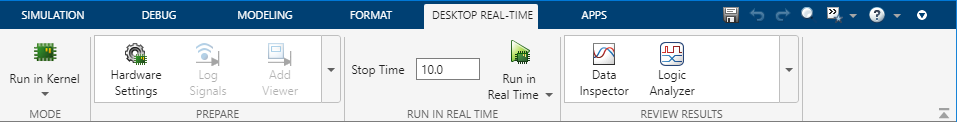
After you use the app to configure the model for Simulink Desktop Real-Time, you can perform these and more tasks from the Desktop Real-Time tab in the Simulink Editor.
Use the actions in the Mode section to select the simulation mode.
UI Control | Description |
|---|---|
|
| Compile model into real-time application and run the application on desktop computer in real time. Monitor signals and tune parameters (external mode). For more information, see Real-Time Execution in Run in Kernel Mode. |
|
| Communicate with hardware inputs and outputs in real-time (normal mode). For more information, see Real-Time Execution in Connected IO Mode. |
Use the actions in the Prepare section to configure the model and tune parameters.
UI Control | Description |
|---|---|
|
| Configure model to run on hardware. The Configuration Parameters dialog box opens. |
|
| Send signal to the Simulation Data Inspector and workspace. Select one or more signals before using this button. |
|
| Add a viewer to the selected signals. Select one or more signals before using this button. |
|
| Allocate memory and make signals observable when using a Floating Scope. Select one or more signals before using this button. |
|
| Show table to manage signal logging and viewing. The Signal Table tab opens at the bottom of the Simulink Editor. |
|
| Configure logging. The Data Inport/Export tab of the Configuration Parameters dialog box opens. |
|
| Launch external mode control panel. The control panel opens. |
|
| If this button is toggled on, you can defer the update of block parameters until you click Update All Parameters or toggle off this button. For more information, see Tune Parameters by Using Hold Updates and Update All Parameters. |
|
| Update all parameters on hardware. For more information, see Tune Parameters by Using Hold Updates and Update All Parameters. |
Remove Hardware Configuration Remove hardware configuration from this model | Remove hardware configuration from this model. The code generation target
is set to |
Use the actions in the Run in Real Time section build the model and run the real-time application.
UI Control | Description |
|---|---|
|
| Compile model into real-time application and run the application on the desktop computer in real time. Monitor signals and tune parameters. For more information, see Execute Real-Time Application in Run in Kernel Mode by Using Run in Real Time. |
|
| Generate executable application. For more information, see Execute Real-Time Application in Run in Kernel Mode by Using Step by Step Commands. |
|
| Connect model to application on hardware. For more information, see Execute Real-Time Application in Run in Kernel Mode by Using Step by Step Commands. |
|
| Start monitoring signals and tuning parameters. For more information, see Execute Real-Time Application in Run in Kernel Mode by Using Step by Step Commands. |
|
| Stop application on hardware an disconnect model. For more information, see Execute Real-Time Application in Run in Kernel Mode by Using Step by Step Commands. |
Use the actions in the Review Results section instrument the model and observe outputs.
UI Control | Description |
|---|---|
|
| View logged data in the Simulation Data Inspector. |
|
| Visualize, measure, and analyze transitions and states over time in the Logic Analyzer. |

Open the Simulink Desktop Real-Time App
In the Apps gallery, under Real-Time Simulation and Testing, click Simulink Desktop Real-Time. The Desktop Real-Time tab opens.
Examples
Version History
Introduced in R2019bSelect a Web Site
Choose a web site to get translated content where available and see local events and offers. Based on your location, we recommend that you select: United States.
You can also select a web site from the following list
Americas
- América Latina (Español)
- Canada (English)
- United States (English)
Europe
- Belgium (English)
- Denmark (English)
- Deutschland (Deutsch)
- España (Español)
- Finland (English)
- France (Français)
- Ireland (English)
- Italia (Italiano)
- Luxembourg (English)
- Netherlands (English)
- Norway (English)
- Österreich (Deutsch)
- Portugal (English)
- Sweden (English)
- Switzerland
- United Kingdom (English)
Asia Pacific
- Australia (English)
- India (English)
- New Zealand (English)
- 中国
- 日本Japanese (日本語)
- 한국Korean (한국어)